Baker Hughes

Summer ‘23

Mechanical Engineering Internship

A 3D rendering of a white electronic device, possibly a toaster or similar appliance, with slots on top and a handle on the side.

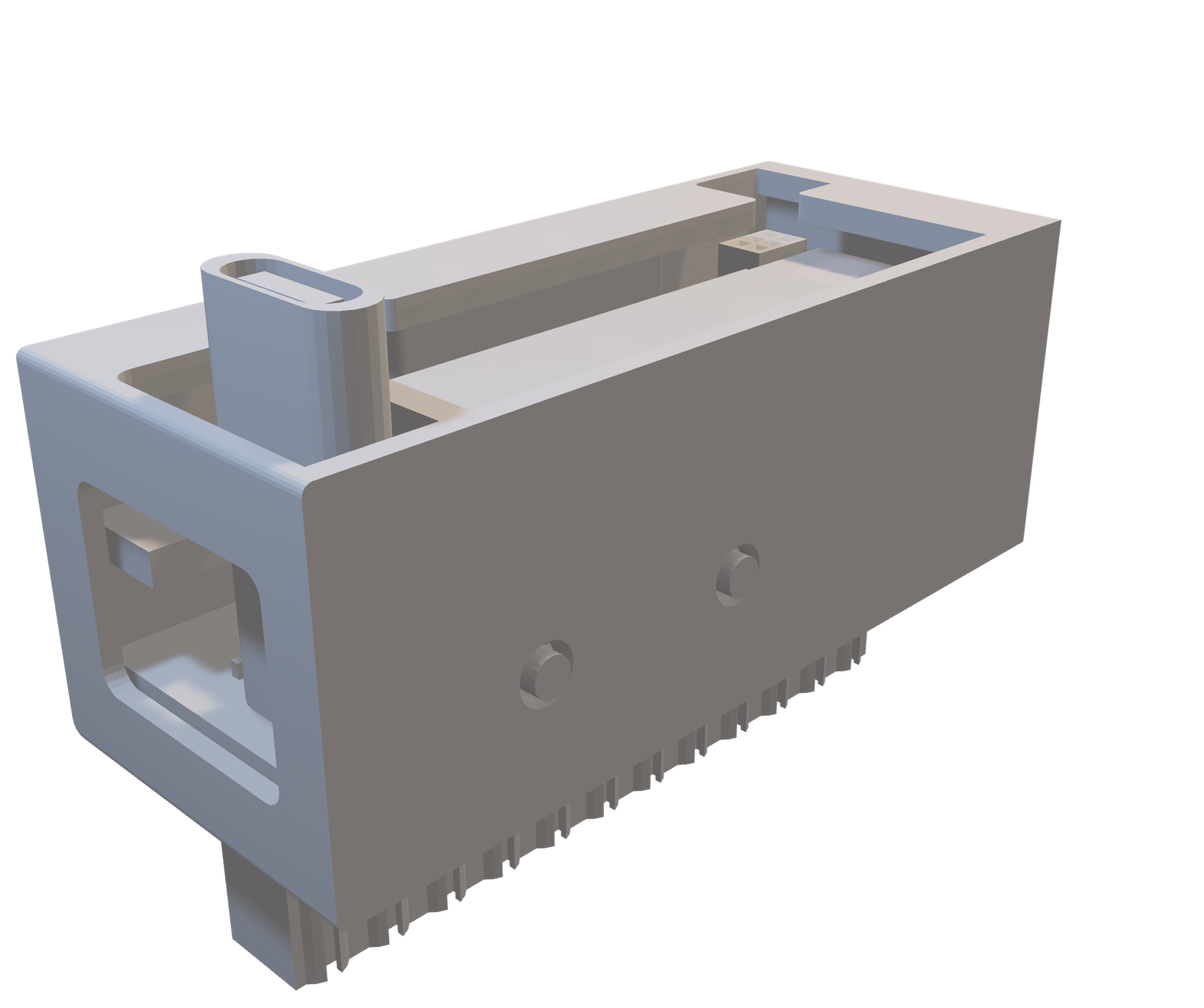
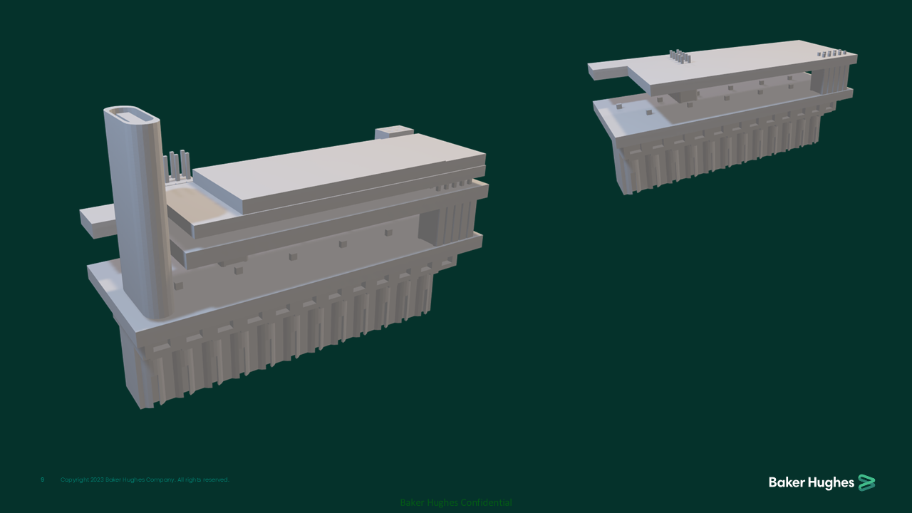
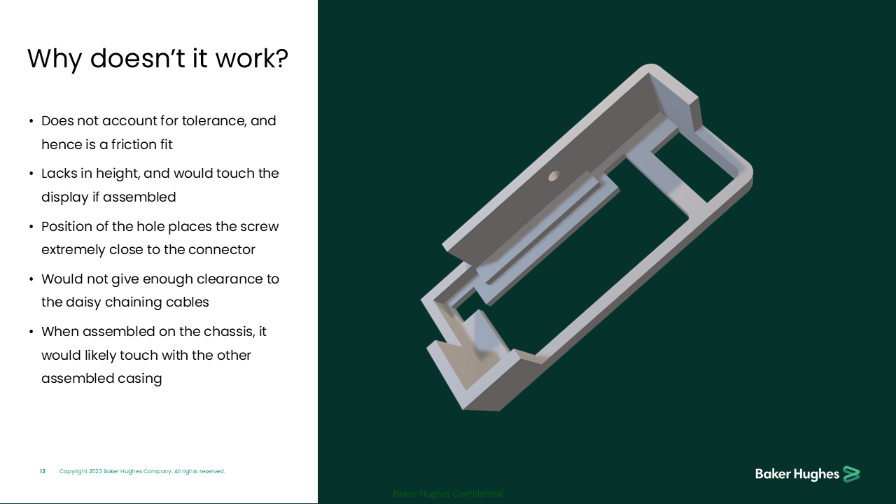
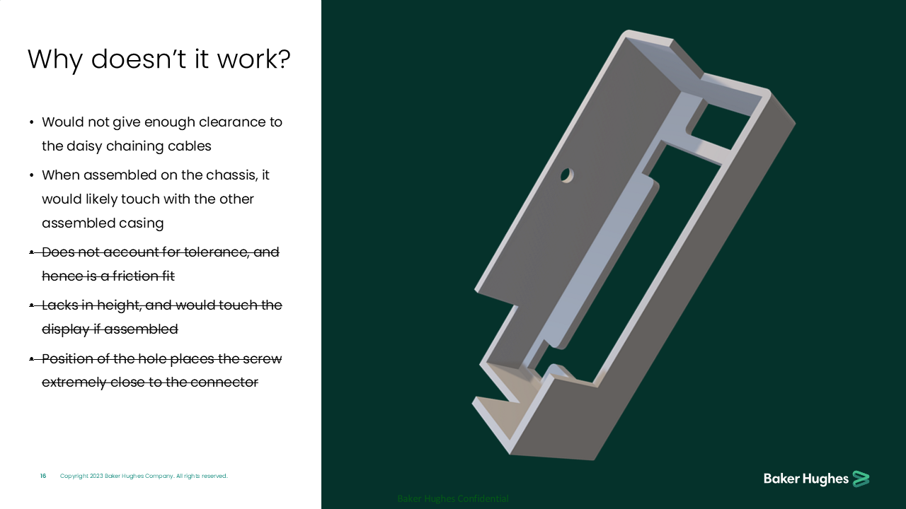
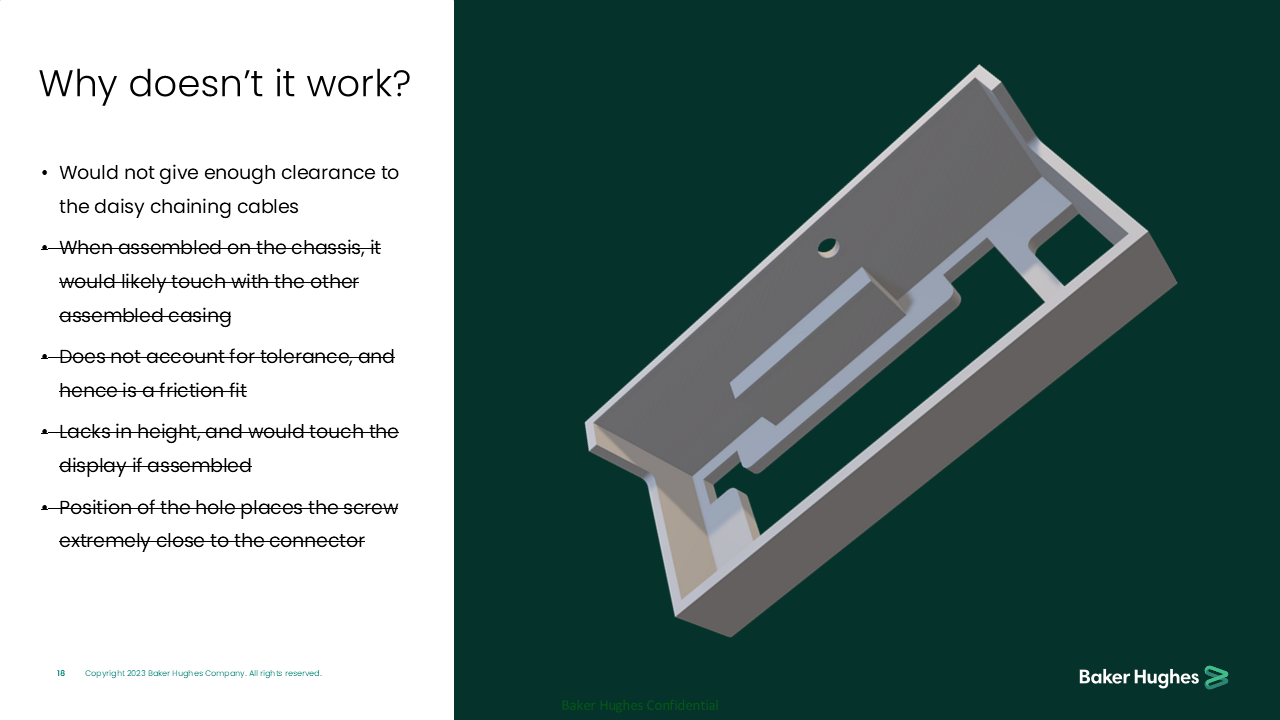
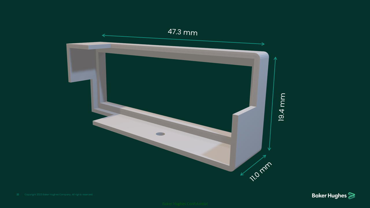
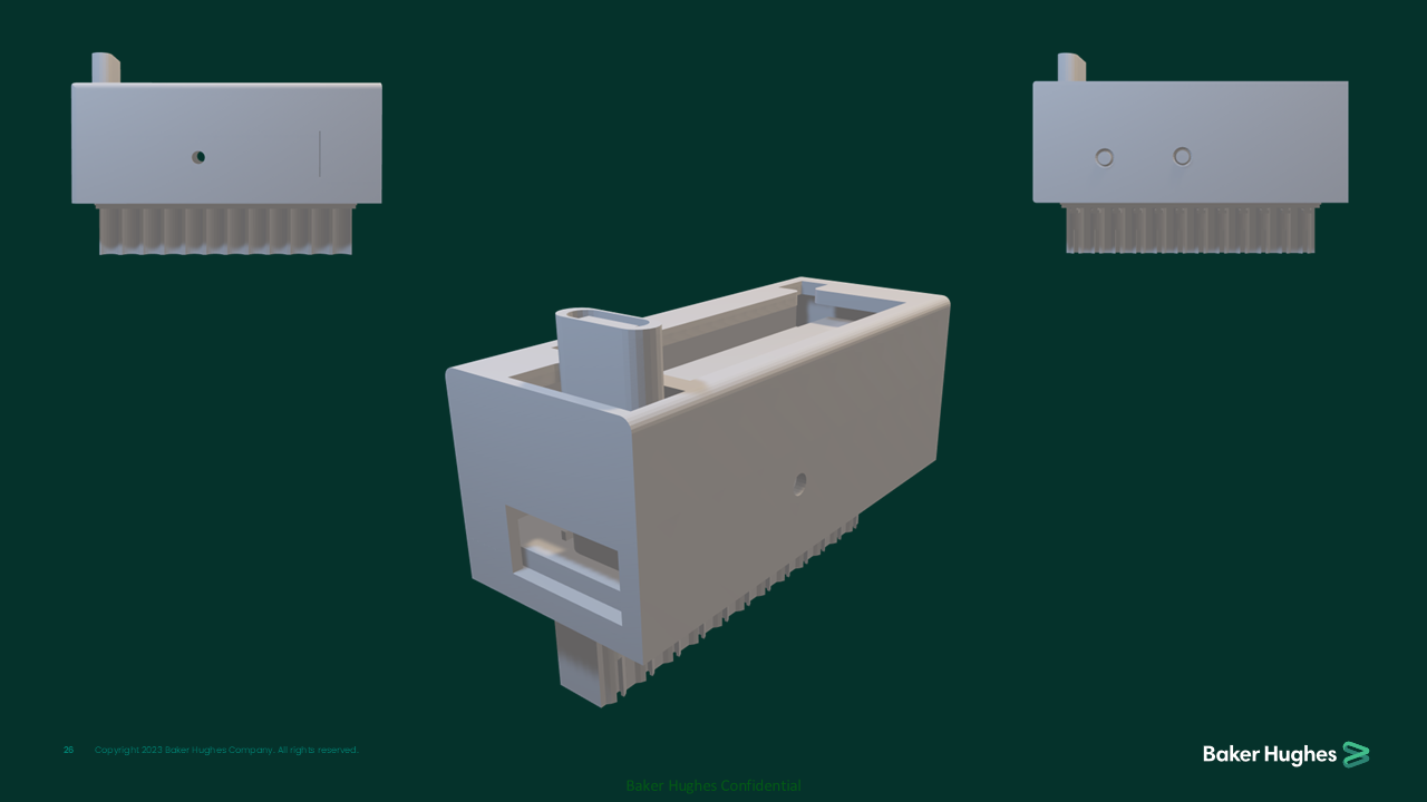
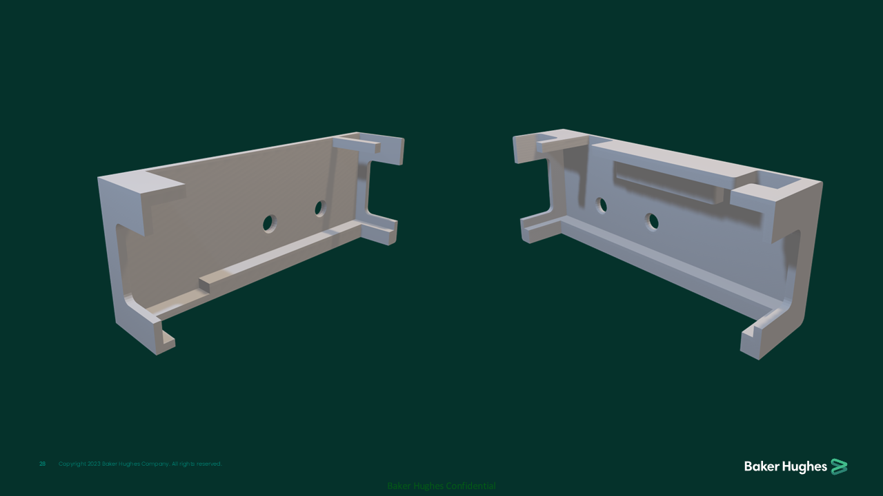
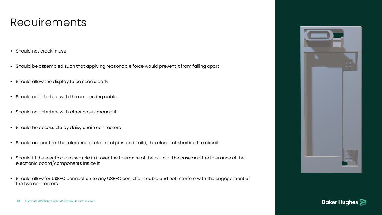
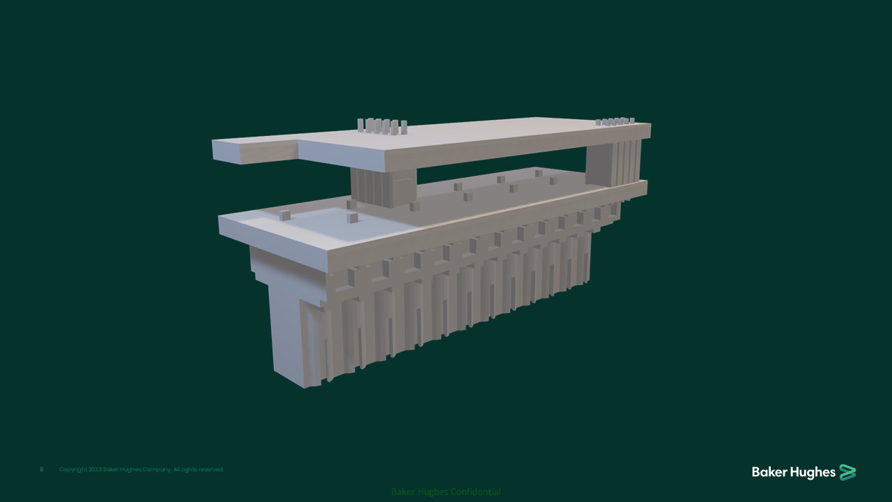
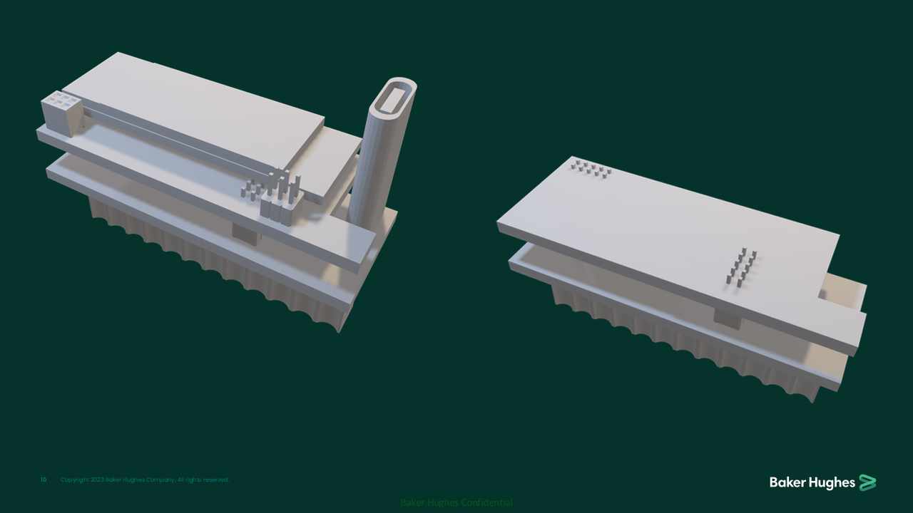
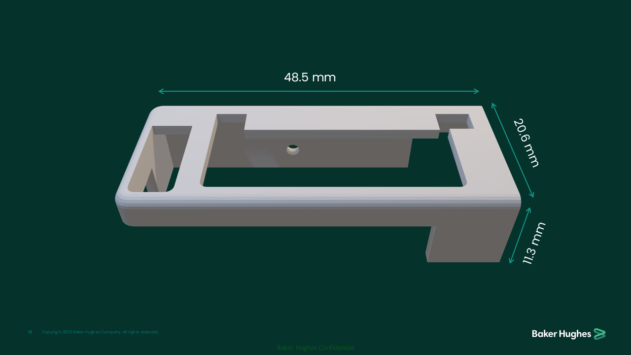
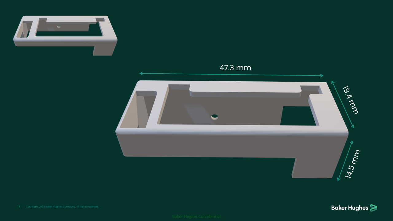
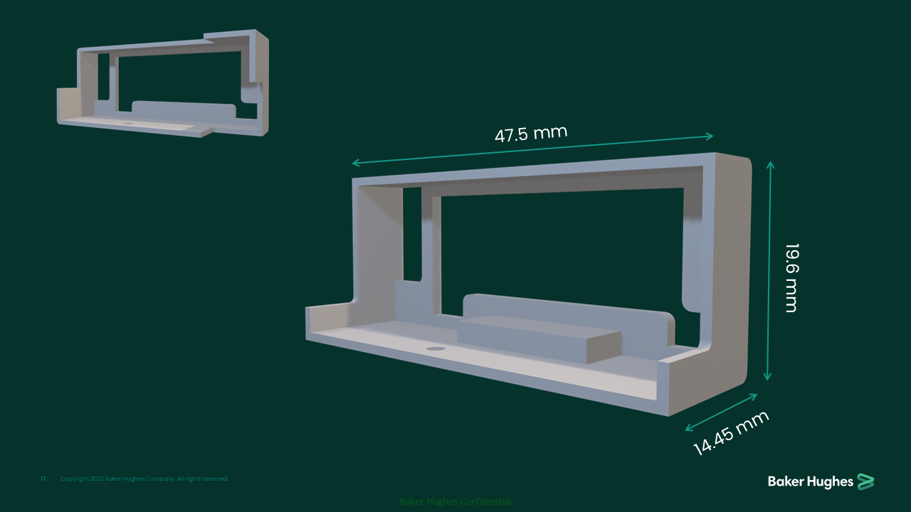
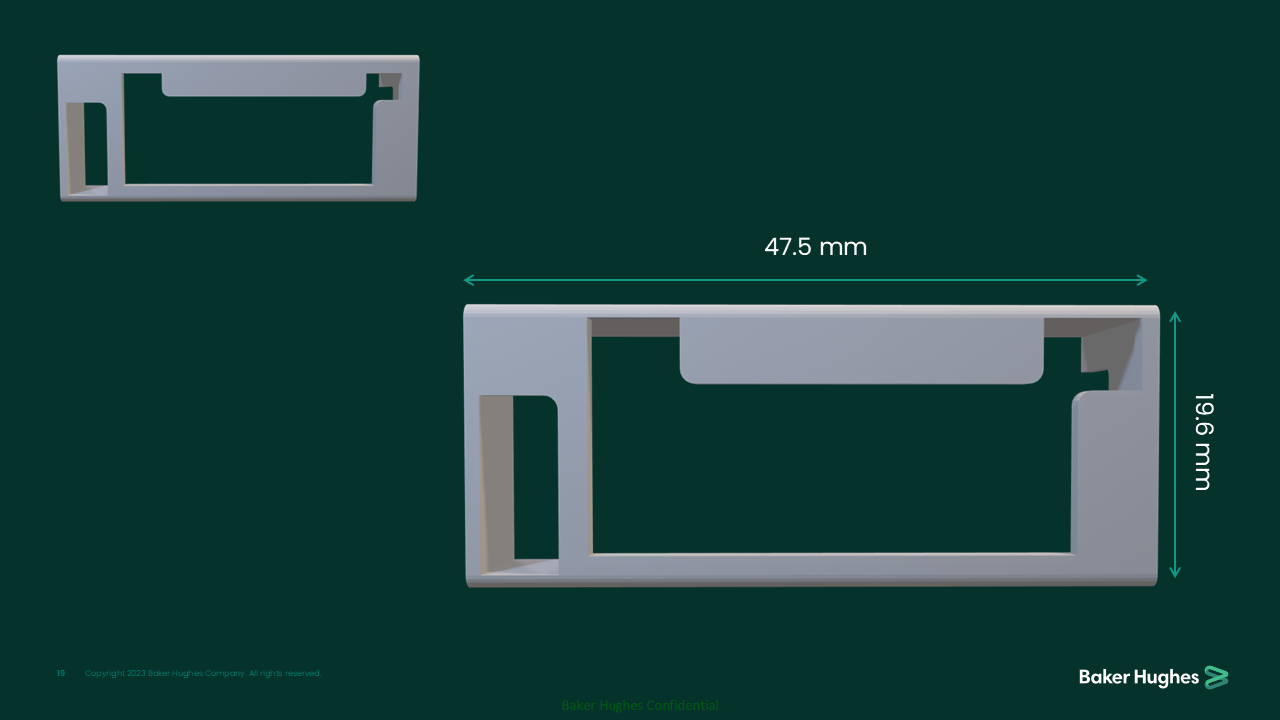
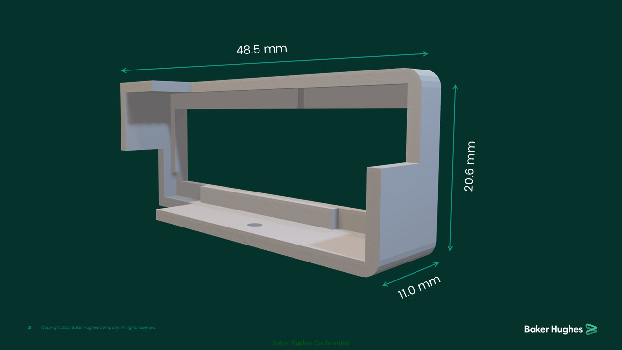
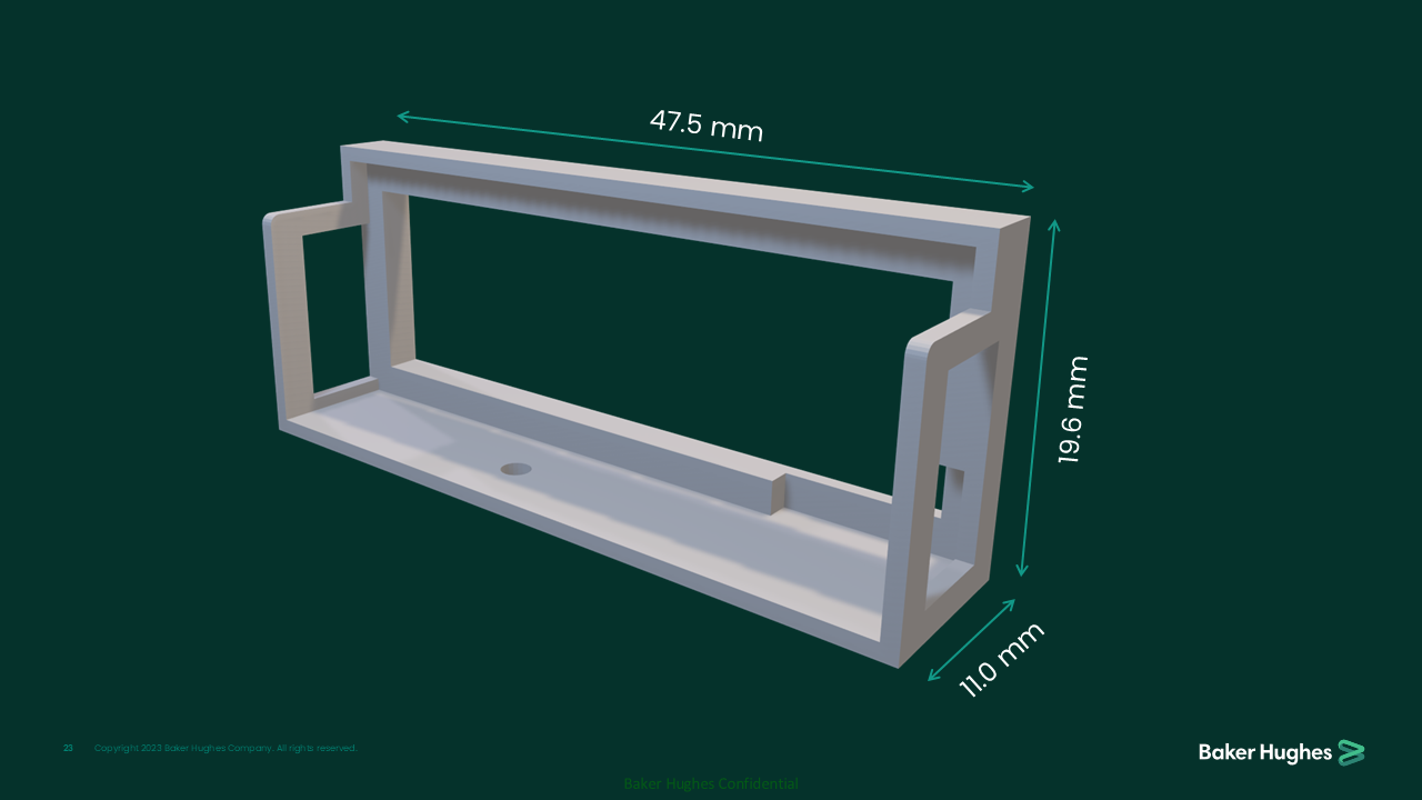
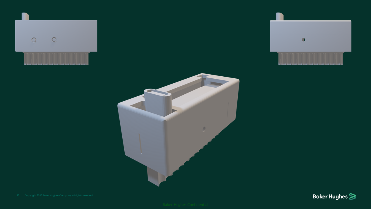
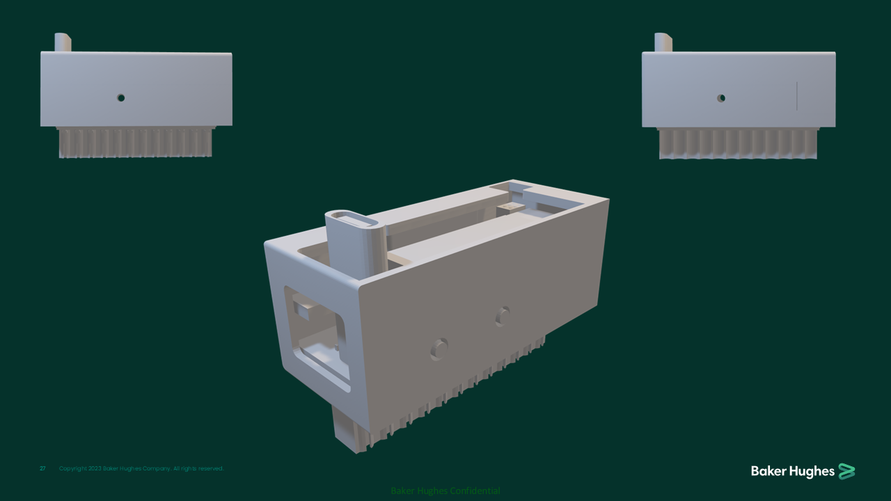
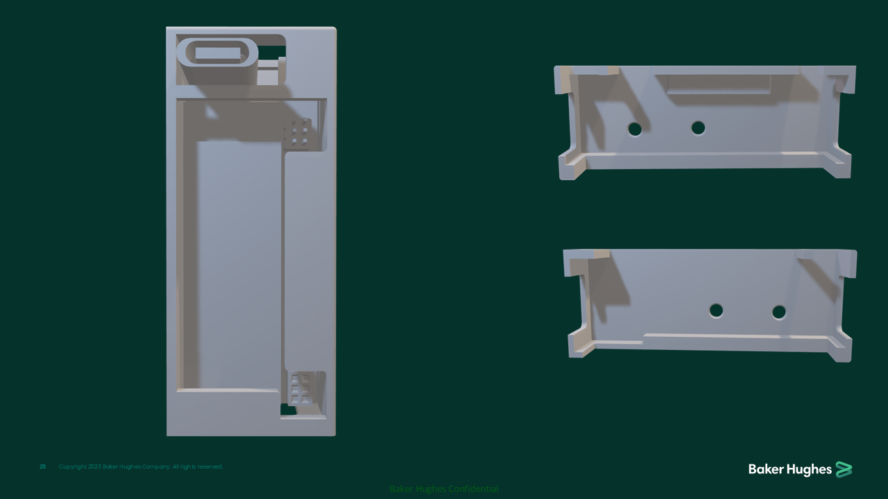
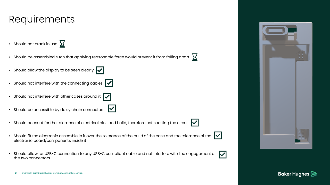
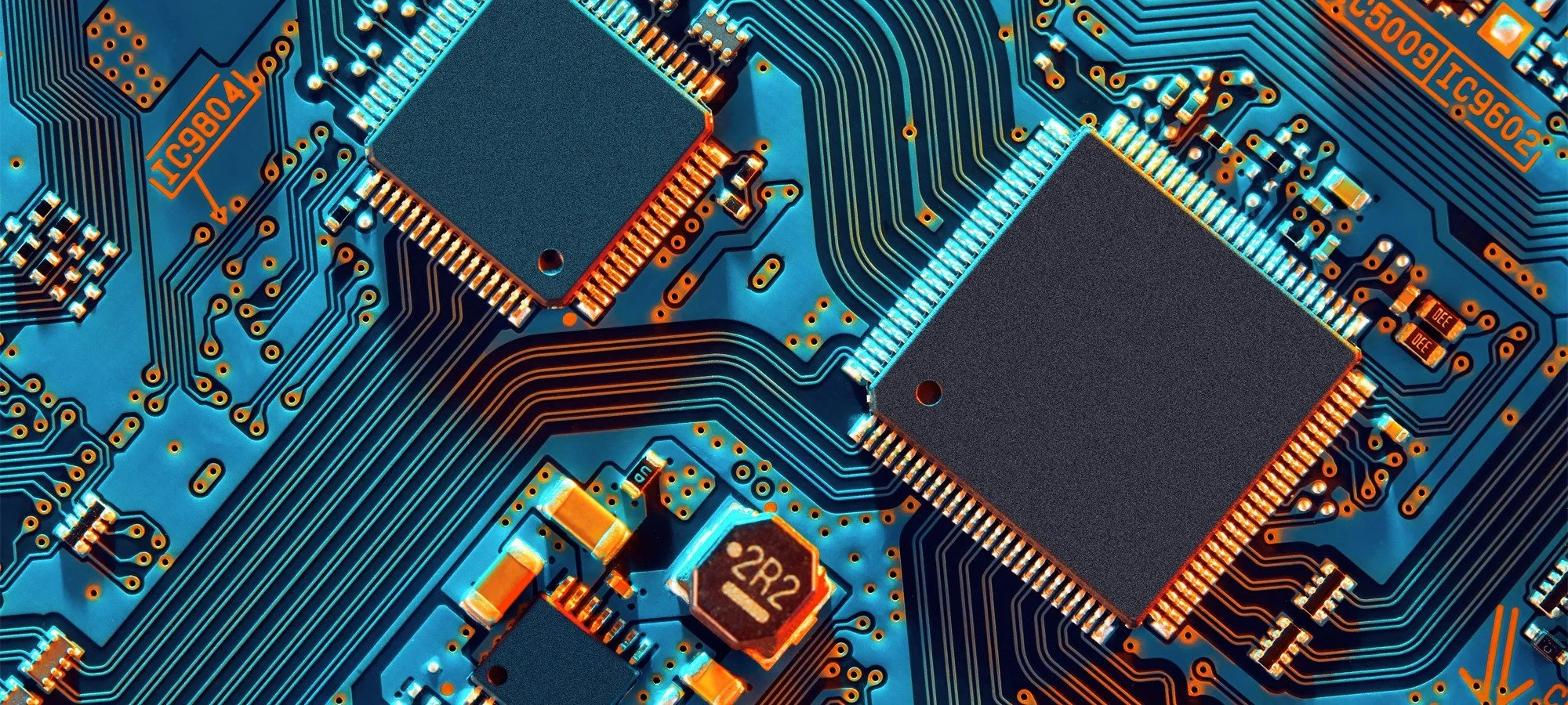
The Leviathan Casing project involved designing an enclosure that securely houses electronic components while ensuring structural integrity, cable clearance, and heat dissipation. The casing needed to accommodate tolerance variations, daisy-chain connectivity, and USB-C compatibility without shorting circuits or obstructing displays. Multiple iterations refined the design to meet manufacturability and functional requirements.

Diagram of a mechanical rotor being rotated clockwise inside a circular housing with yellow and gray sections, and arrows indicating rotational movement.

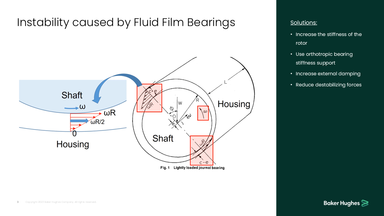
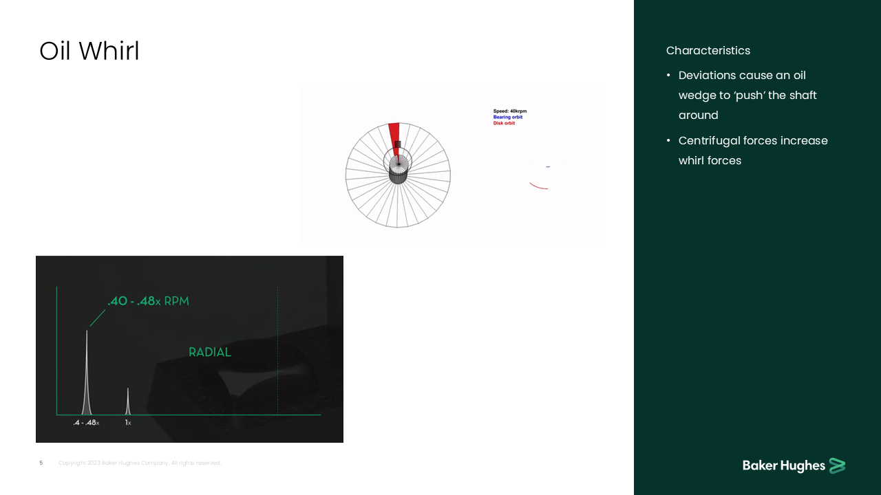
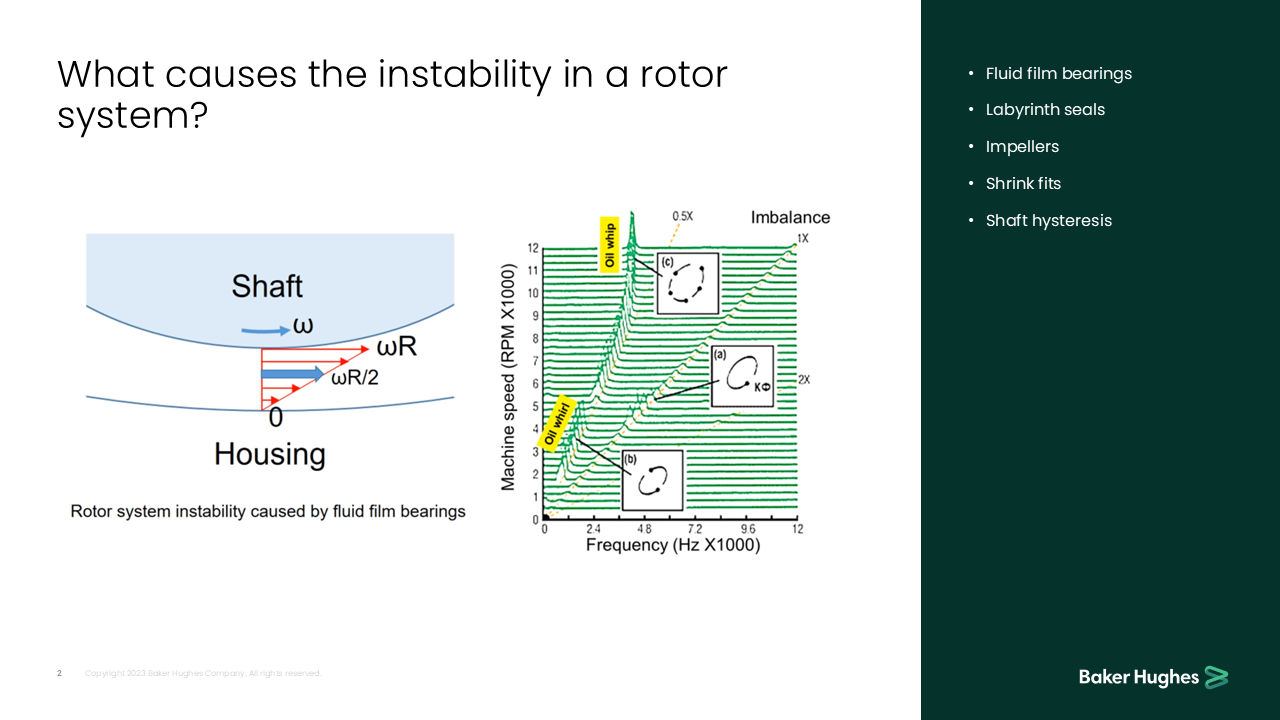
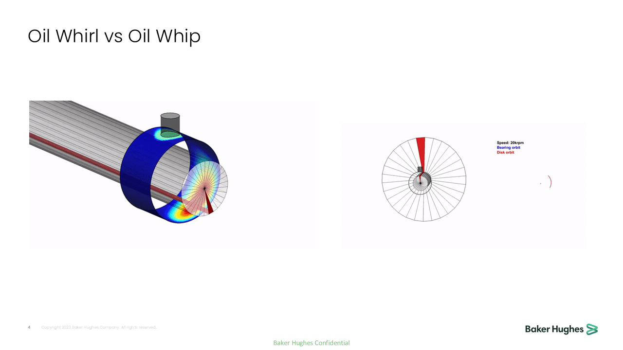
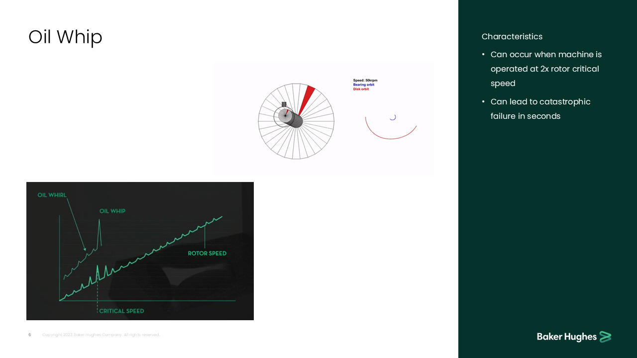
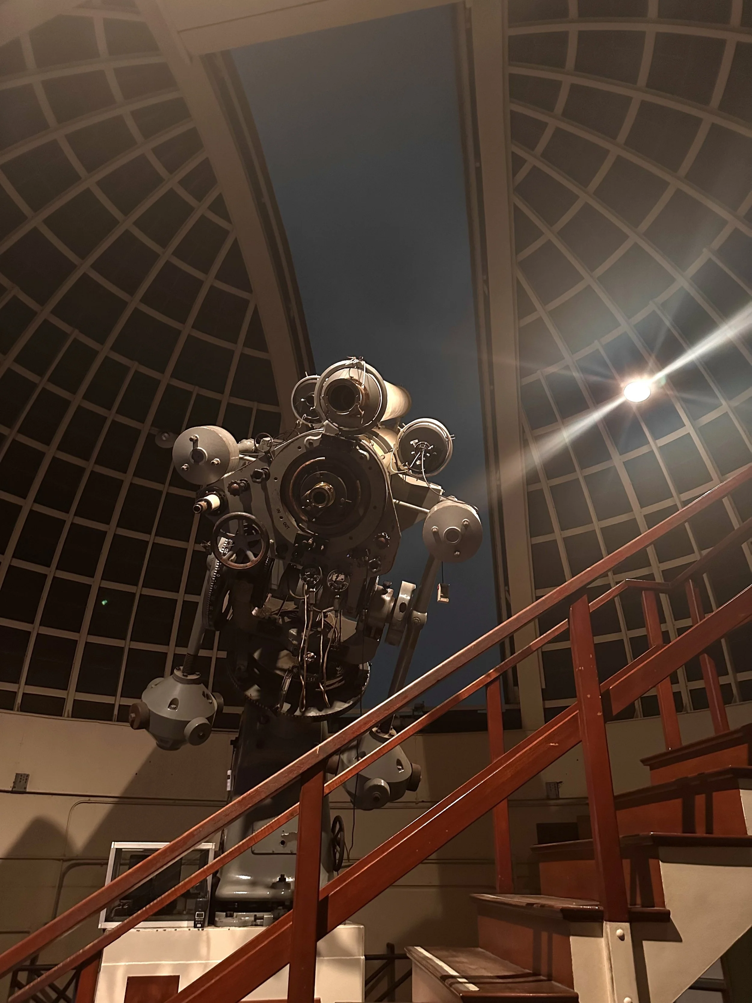
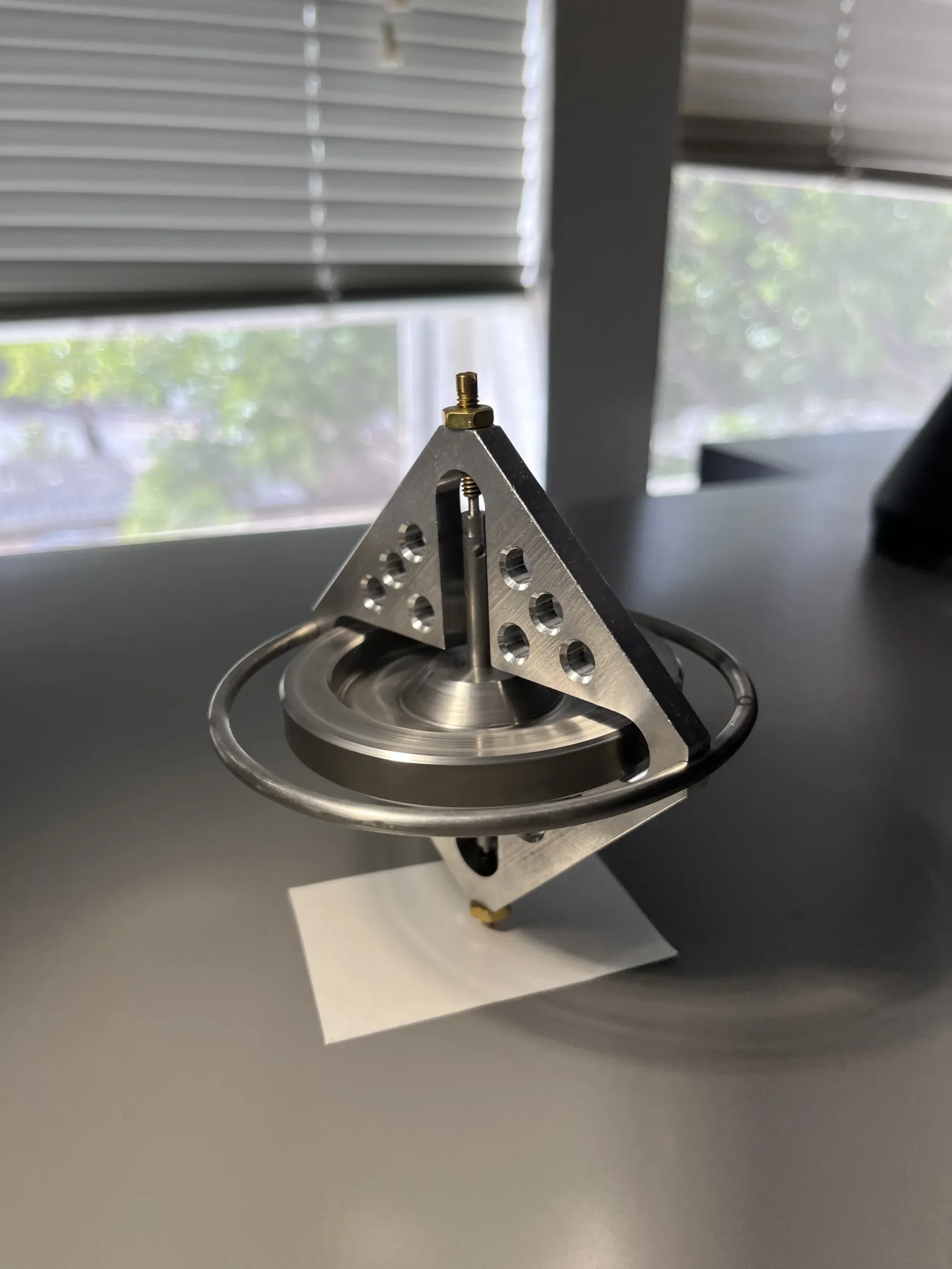
The Rotor Kit project focused on fluid-induced instabilities in rotating machinery, particularly oil whirl and oil whip phenomena in fluid film bearings. By analyzing rotor stiffness, damping strategies, and destabilizing forces, I explored ways to mitigate these effects and improve bearing design for long-term reliability. This work contributes to preventing catastrophic failures in high-speed rotating systems.

Slide title that reads 'Leviathan Casing' with a large abstract teal and white graphic on the right side, and the Bakers Hughes logo at the bottom right corner.
Title slide of presentation with the text 'Dummy PCB' and a large abstract green shape on a dark background.
3D render of a large industrial building with multiple levels and a tall cylindrical tower on the left side, shown from two different angles.
Slide with green and teal abstract shapes, titled 'Top Case,' with Baker Hughes logo and copyright info at the bottom.
Diagram showing a disassembled component with a list of reasons why it doesn't work, including issues with tolerance, height, hole placement, clearance, and assembly contact.
Diagram of a metal casing with cutouts and a screw hole, used to illustrate component assembly
Slide from a presentation with the title 'Why doesn't it work?' and a bullet list explaining technical issues, next to a 3D rendering of a metal component with cutouts.
A presentation slide titled 'Bottom Case' with abstract teal and dark green shapes. The slide includes a footer with copyright information and the Baker Hughes logo.
A 3D rendering of a rectangular electronic component holder with dimensions labeled in millimeters: 47.3 mm wide, 19.4 mm high, and 11.0 mm deep, with a circular hole at the base.
A presentation slide with the word 'Assembly' and a large abstract teal logo on a dark green background, with the 'Baker Hughes' logo at the bottom right corner.
Three metallic electronic components with fins and holes, displayed against a dark green background.
Two metallic L-shaped brackets with holes for screws, positioned parallel to each other, on a dark green background.
Requirements list on a presentation slide with a dark green border on the right and an illustration of an electronic device case.
Slide with the title 'Rotor Dynamic Instability' and the Baker Hughes logo at the bottom right corner.
Diagram showing instability caused by fluid film bearings in a rotating shaft system, with labeled components including shaft, housing, and bearing. Includes solution points like increasing stiffness and damping.
A presentation slide titled 'Oil Whirl' showing diagrams and text about rotor dynamics. The slide includes a diagram of a rotor's speed and bearing orbit, a graph illustrating RPM levels, and a list of characteristics of oil whirl phenomena.
Slide titled 'Project Scope' with bullet points outlining guidelines for electronic and mechanical assembly, including safety, visibility, and compatibility considerations. The logo of Baker Hughes at the bottom right corner.
3D digital model of a mechanical or industrial component with multiple layers and structural features, rendered in gray against a dark background.
Digital render of two electronic circuit boards with various components on a green background, labeled as Baker Hughes.
A 3D-printed rectangular object with dimensions labeled as 48.5 mm in length, 20.6 mm in width, and 11.3 mm in height. The object appears to have a hollow rectangular section in the middle and a protruding section on one side. The background is dark green, and there is a small logo in the bottom right corner.
3D rendered image of a white rectangular mechanical or electronic component with dimensions 47.3 mm by 19.4 mm by 14.5 mm, placed on a dark green background. The component has cutouts and holes, and the measurements are displayed in millimeters.
3D diagram of a rectangular structural component with dimensions labeled: 47.5 mm by 19.6 mm by 14.45 mm, shown from two angles.
3D-rendered image of a metallic rectangular component with detailed measurements, placed on a dark green background. The dimensions indicate a length of 47.5 mm and a height of 19.6 mm.
3D rendering of a rectangular metal or plastic component with dimensions marked as 48.5 mm by 20.6 mm by 11.0 mm, featuring an open center and various cutouts and notches, set against a dark green background with measurements labeled.
3D model of a rectangular metallic frame with dimensions labeled as 47.5 mm in length, 19.6 mm in height, and 11.0 mm in depth, on a dark green background.
3D rendering of a metallic electronic component, resembling a connector or a module, with two smaller modules above it.
Three computer hardware components, including a close-up of a white circuit board with fins, a grey plastic connector housing, and a smaller grey component with fins, arranged against a dark background.
A plastic wall mount box with two separate white clips, one on the top and one on the bottom, designed to hold electronic devices or wiring.
A set of requirements for electronic enclosures or cases, listed with checkmarks next to each point, alongside a 3D rendering of an electronic case or enclosure on a green background.
Diagram illustrating rotor system instability caused by fluid film bearings with a graph showing machine speed versus frequency, highlighting oil whirl and oil whip phenomena, and a shaft within a housing.
Comparison chart showing differences between oil whirl and oil whip in a rotating machinery part with diagrams and labeled data.
slide titled 'Oil Whip' with a diagram of a rotating machine showing the speed, bearing orbit, and disk orbit, a graph illustrating oil whirl, oil whip, rotor speed, and critical speed, and a list of characteristics stating that oil whip can occur at twice rotor critical speed and can cause catastrophic failure within seconds.